|
|
|
Kto jest w sklepie?
Sklep przegląda 5638 gości |
|
Kategorie
|
|
Informacje
|
|
Polecamy
|
|
|
 |
|
|
Dla tego produktu nie napisano jeszcze recenzji!
 ;
Wszystko w porządku.
Instrukcja czytelna i kompletna.
Dziękuję.
all right!
thank you.
;
Bardzo dobra instrukcja. Zawiera wszystko co potrzeba, polecam!
 ;
Instrukcja jest OK. Schematy czytelne, opisane niektóre procedury.
;
Instrukcja bardzo czytelna. zawiera co potrzeba. Polecam
;
...instrukcja serwisowa w pełni czytelna i kompletna. Dziękuję!
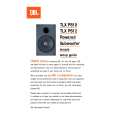
Powered Subwoofer
TLX PS12
pliers, gently heat and remove cut lead from hole in edge or PCB. Clean insulator and seating area on back of panel. Coat both sides of insulator with silicon (white) thermal compound (unless silicone rubber pads are provided), position it centered on back of device with holes aligned. Insert leads into PCB then place pair over hole in panel; ensure hole in insulator is aligned. Insert screw from far side, pass shoulder bushing over screw and carefully seat shoulder in hole in tab, add flat washer, lock washer and nut (finger tight). Center insulator tighten screw first then solder all three leads in respective slots with full fillet, being careful not to bridge pads. Use ohmmeter to verify there is no short from tab of transistor to panel, or between pads.
Connect sub-woofer system to a music source. Play at high level while checking for air leaks around panel edge, driver, panel jacks and controls, and voice coil problems such as rubbing or loose turns. With the crossover "frequency" set to 50Hz, very little of the voice content should be heard.
4. LIST OF SAFETY COMPONENTS REQUIRING EXACT REPLACEMENTS
F1 Fuse SLOW BLO 2.0A 250v GMC 20mm UL approved. Fuse holder. Use only factory replacement.
FH
PWR CORD SPT-2 better with polarized plug, UL appoved wired with the hot side to fused side. Use with UL approved panel strain relief only. Never operate amplifier with load connected when PC assembly is not attached to panel or when any of output transistors is not properly screwed to panel. After repair, inspect for possible safety hazards, including loose hardware, missing lock washers, correct fuse and lead dress of primary wires (these must be held in position with cable ties so that they cannot touch secondary components). With ohmmeter, check that panel is connected to signal ground. XF transformer. use only factory replacement. Bridge diode. Use only factory replacement. 6800uF, 63V electronic filter caps. Be sure replacement part is at least the same working voltage and capacitance rating. Also the lead spacing is important. Incorrect spacing may cause premature failure due to internal cabinet pressures and vibration. K1 It is essential that the following safety insulation test be performed prior to returning the Power Sub-Woofer to the customer, using one of the following methods: A) Insulation Resistance Test With a 500VDC Insulation Tester, Check insulation from the outer metal contact of the RCA jack (chassis) to the line neutral of AC cord. Resistance should be >100M�. B) Hi-Pot Test If a UL approved Hi-Pot tester is available, test line & neutral of AC cord to outer shell of RCA jack (chassis) at 1100VAC for 2 seconds. Observe all of instrument manufacturer's instructions and safety warnings in performing this test. Safe operating area relay to protect output devices. Use only factory replacement. 5.6� .5W METAL FILM, non flammable.
BD1
C36, 37
R64
6
|
|
|
> |
|